Galvanized Coating Thickness Measurement
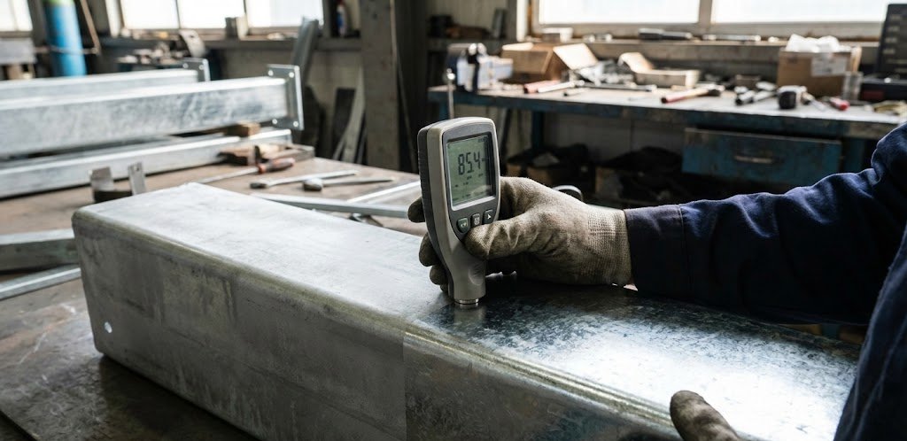
Galvanized coating thickness measurement is the process of determining the thickness of the zinc layer protecting a steel surface, typically expressed in micrometers (µm). One micrometer is equal to one-thousandth of a millimeter. These measurements help verify whether the coating meets project requirements and applicable standards.
For reliable measurement, the following factors should be considered together:
- The instrument must be suitable for measuring zinc coatings on steel.
- The measurement surface should be clean and dry.
- The instrument should be verified before measurement.
- Multiple readings should be taken from representative areas of the component.
- Results should be evaluated according to the applicable specification or standard.
A single measurement does not represent an entire component. For standardized acceptance, readings should be grouped and evaluated according to the sampling rules of the applicable standard rather than relying only on a simple minimum, maximum, or overall average.
Why Is Galvanized Coating Thickness Measured?
Galvanizing protects steel against corrosion caused by moisture, atmospheric exposure, pollutants, and other environmental conditions. Zinc coating thickness is one of the primary measurable characteristics used to evaluate the finished coating.
A bright or visually smooth surface does not necessarily indicate adequate coating thickness. Two galvanized components with similar appearances may have different coating thicknesses.
Thickness measurement is commonly performed to:
- Verify compliance with project specifications
- Confirm applicable coating requirements
- Monitor production quality
- Evaluate coating distribution
- Identify potentially non-compliant areas
- Create quality inspection records
Coating thickness alone does not determine service life. Environmental corrosivity, component design, steel chemistry, exposure conditions, and coating continuity also influence long-term performance.
Which Methods Are Used to Measure Galvanized Coating Thickness?
For zinc coatings on steel, portable magnetic coating thickness gauges are among the most commonly used instruments for routine non-destructive inspection.
Laboratory methods can be used when more detailed analysis is required.
| Measurement Method | Typical Application | Main Advantage | Key Consideration |
|---|---|---|---|
| Magnetic thickness gauge | Production and field inspection | Fast and non-destructive | Correct probe and verification are required |
| Gravimetric stripping method | Laboratory evaluation | Determines coating mass | Destructive to the tested coating |
| Microscopic cross-section | Detailed coating analysis | Directly shows coating structure | Requires sectioning a sample |
| Dimensional comparison | Limited special applications | Can provide supplementary information | Not a substitute for standardized coating measurement |
For routine inspection of batch hot-dip galvanized fabricated steel, magnetic measurement is generally the most practical method.
How Is Galvanized Coating Thickness Measured with a Magnetic Gauge?
A magnetic coating thickness gauge determines the distance between the probe and the ferromagnetic steel substrate through the non-magnetic zinc coating.
A typical measurement procedure includes:
- Review the component information. Identify the material, geometry, steel thickness, and applicable acceptance requirements.
- Prepare the measurement surface. The area should be clean, dry, and free from loose contamination that could interfere with the probe.
- Verify the instrument. Follow the instrument manufacturer’s procedure using suitable reference standards, shims, or an appropriate uncoated substrate where required.
- Define inspection areas. Select representative areas according to the component and applicable standard.
- Position the probe correctly. The probe should be placed steadily on the surface according to the instrument instructions.
- Take multiple readings. Several readings are generally required to characterize an inspection area.
- Record the results. Document readings and calculated values according to the specified inspection procedure.
“A number appearing on the display does not by itself prove that the measurement is valid.”
Surface geometry, probe position, instrument verification, and sampling method all influence measurement reliability.
How Should Measurement Locations Be Selected?
Measurement locations should represent the component rather than simply being the easiest flat surfaces to reach.
Depending on the product, inspection may consider:
- Large flat surfaces
- Different sections of the component
- Curved areas
- Welded areas
- Drainage-related locations
- Areas with visibly different coating characteristics
However, measurements taken very close to edges, corners, holes, or abrupt geometric transitions can be influenced by the instrument’s magnetic field.
The applicable measurement standard and gauge manufacturer’s instructions should therefore be followed when determining acceptable probe locations.
For pipes and curved components, a probe suitable for the relevant curvature may be required.
How Are Measurement Results Evaluated?
Before results are interpreted, the applicable acceptance criteria must be identified.
These may come from:
- Project specifications
- Customer requirements
- An approved inspection plan
- The applicable galvanizing standard
For batch hot-dip galvanized fabricated iron and steel articles, EN ISO 1461 is commonly used as a reference for coating requirements and test methods.
Under standardized inspection, individual readings are generally used to determine local and mean coating thickness values according to defined sampling rules.
For this reason, it is not always correct to reject a component simply because one isolated instrument reading is lower than a nominal value. The result must be evaluated according to the relevant standard’s measurement and acceptance procedure.
Common Measurement Errors
Small procedural errors can produce misleading readings.
Common problems include:
- Measuring a dirty or wet surface
- Failing to verify the instrument
- Holding the probe incorrectly
- Measuring too close to an edge or hole
- Using an unsuitable probe on a curved surface
- Relying on a single reading
- Measuring over foreign material or repair coatings without accounting for them
- Failing to document measurement locations
- Ignoring instrument temperature limitations
If readings in one area vary significantly, the surface and instrument should be checked before a conclusion is reached.
Effects of Surface Condition
Galvanized coatings are not perfectly smooth at a microscopic level. Surface roughness can therefore create some variation between individual readings.
Areas containing:
- Zinc accumulations
- Repair material
- Foreign contamination
- Ash residues
- Unusual surface projections
may not represent the normal coating and should be evaluated carefully.
The objective is to obtain representative measurements of the galvanized coating rather than simply collecting the highest or lowest values available.
Coating Thickness and Standards
Minimum coating requirements depend on the product and applicable standard.
For batch hot-dip galvanized fabricated steel, EN ISO 1461 defines coating requirements according to relevant material categories and steel thickness.
Other products may be governed by different standards, including:
- Continuously galvanized sheet
- Fasteners
- Centrifuged articles
- Electroplated zinc coatings
- Specialized steel products
The correct standard should therefore be identified before measurements are interpreted.
Measurement Approach for Avrasya Galvaniz Projects
For projects processed through Avrasya Galvaniz, coating requirements should ideally be defined during the quotation and technical review stage.
Important project information can include:
- Component dimensions
- Steel thickness
- Steel characteristics
- Product geometry
- Intended application
- Applicable galvanizing standard
- Inspection requirements
- Documentation requirements
Where coating thickness inspection is requested, representative measurements can provide a more meaningful assessment than relying on a single value.
Recording measurement areas together with component or batch identification can also improve traceability.
Checklist for Reliable Coating Thickness Measurement
Before accepting measurement results, confirm that:
- The instrument is suitable for zinc on steel.
- The probe is appropriate for the component geometry.
- The surface is suitable for measurement.
- The instrument has been verified according to the required procedure.
- Representative inspection areas have been selected.
- Multiple readings have been taken where required.
- Edge and curvature effects have been considered.
- Measurement locations are documented where necessary.
- Results are evaluated according to the applicable standard or specification.
Reliable Measurement Requires the Right Method
Galvanized coating thickness measurement provides valuable information about coating compliance and production quality when it is performed with the correct instrument and sampling procedure.
For routine inspection of hot-dip galvanized fabricated steel, magnetic gauges offer a fast and non-destructive method. More detailed laboratory techniques can be used when coating structure, mass, or failure mechanisms require further investigation.
For Avrasya Galvaniz projects, evaluating representative coating thickness measurements together with surface condition, component geometry, steel characteristics, and applicable standards provides a more reliable basis for determining coating quality.